

|

|

|

|
|
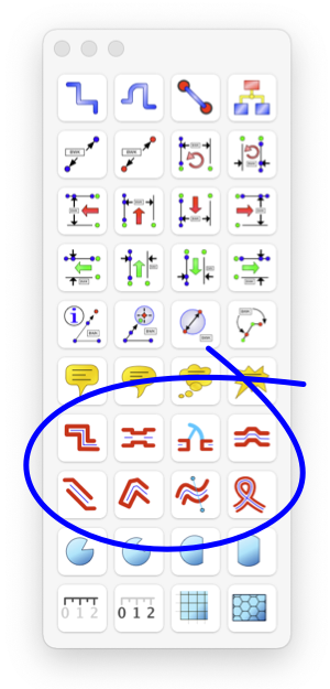
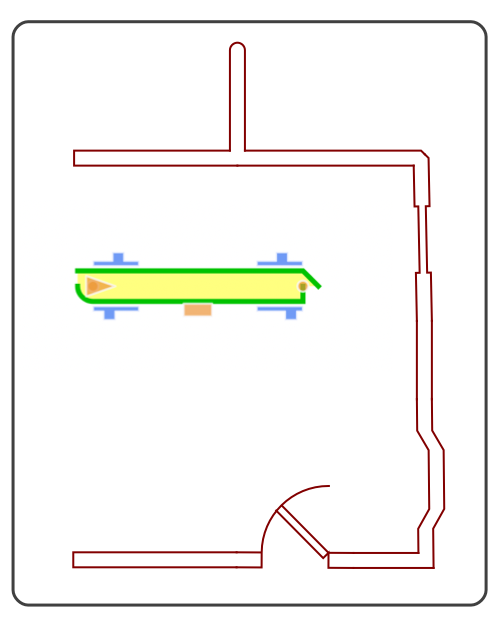
Walls, Ribbons, Windows, and Doors These tools are used to create double path graphics to depict walls windows and doors on architectural drawings. They are also useful in map drawing for depicting roads and intersections. Or they may be thought of as decorative Ribbons, especially when filled with interesting Gradient Fills. The key aspects of a Wall graphic are the thickness and the shape of the ends. Wall elements will "snap" together and automatically adjust these key aspects to form corners and intersections in a logical fashion. It is important to understand and utilize Snap Vertices when working with these elements. Selecting this option or drawing with Grid Snapping On is useful when combining these graphics in a drawing. The orthogonal wall tool (top left of the wall tool group) draws only horizontal and vertical wall objects. The other wall tools provide methods for straight walls at angles, multi-segment straight walls, Bezier path curved walls, and smooth ribbons. Wall will auto-join at coincident ends - unless the Auto-Join parameter is turned off on the Wall Parameter panel, or at least one corner of the wall end is drawn with the Closed or Butt shape form. Either of these methods is used to prevent auto-mating of wall ends. These graphic elements have two paths, one is a master path defining the center line of the wall or ribbon. The other path is an outline of the wall or ribbon which draws the two sides and ends of the wall or ribbon. The stroke and fill parameters have a necessary duplicity that may become confusing to newer users. Two points of advise. First, if you are not using the walls stroke or outline path (the stroke checkbox on Color and Style palette is off) then it is probably not necessary to introduce the complexity of a wall graphic - just use a fat line. Second, if you are new to eazydraw or inexperienced to computer drawing, it may be wiser to avoid wall graphics and use simple lines and Bezier paths for initial drawing projects.

Walls have a defined start and end that effects the "Right" or "Left" side of the wall. This is important only for the Bay Window and Door elements. Most importantly this will effect the direction of the swing of the door. Eight combinations are required for all orientations of a door. These may be achieved selection of the direction and hinge options provided on the Graphic Details Inspector. Adjusting the thickness of one wall element section will automatically adjust all other wall elements "snapped" to the element being adjusted. To control the use of a normal corner or a beveled corner representation: use the end handle to adjust an unsnapped wall element to the beveled configuration (the one with a 45 degree end component). Then bring another wall section up to the prepared element and let them snap - the corner will then be beveled. Duplicating prototype wall elements is a useful technique. Create one wall element and adjust the ends other parameters if appropriate. Then duplicate or copy-paste this element to create new wall sections. This is easier than creating a new wall element and adjusting each time. The Knife tool is useful for forming a T-section or full intersection. Cut an existing wall with the knife - the break will not be noticeable as the ends are automatically adjusted after the cut. Create another perpendicular wall section, then bring it to the cut point. The new element will auto-snap and the end shapes will automatically adjust to form the T shape joint. Repeat with another perpendicular element to form full intersection. A Gradient Fill may be applied to all of these graphic forms. Only two of the Gradient styles are defined for a wall, Horizontal and Vertical. Vertical gradient is applied "across" the path, or normal, at all points, to the center line of the path. Horizontal gradients are defined "along" the path or parallel at all points of the center line of the path. Note that the two free form Bezier wall shapes can have anomalies at vertices or other points along the path. This will occur at points of sharp bends and abrupt direction changes of the paths. These ribbon shapes are drawn and constrained to two dimensions, in a full three dimension world the ribbon would pinch and curl when twisted to conform to the defining path. To form these shapes in only 2 dimensions EazyDraw must apply approximating "fuzzy" logic that is NOT precisely defined for all possible distortions of the ribbon. We have attempted to make certain that for normal non-extreme bends and curves the ribbon is drawn in an expected well defined manner. But if extreme twists and turns are used small artifacts or kinks may appear. In this situation small adjustments of the curve can usually be performed to remove the unwanted artifact or kink. It may help to manually insert vertices near problem intersections. |